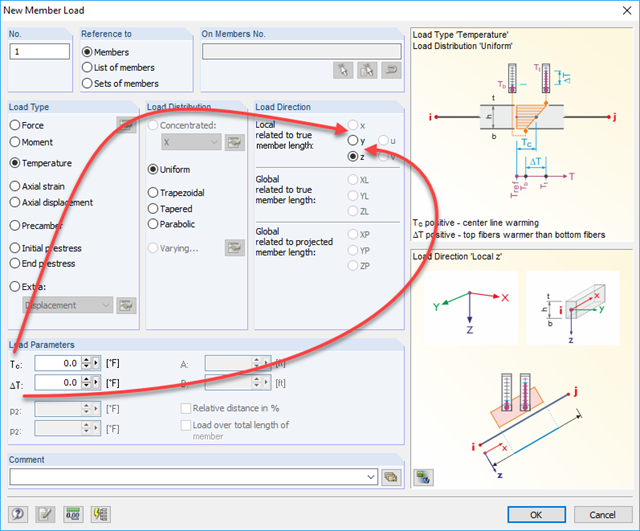
I would like to define a constant temperature load over the cross-section height. Why is it not possible to select the load direction in the local x-direction of the member for this?
I have idealized a taper using a start and end cross-section (calculated in SHAPE‑THIN) and calculated a frame. During the stress calculation in STEEL, the error message "Tapered member contains incompatible cross-sections" appears. What is the error?
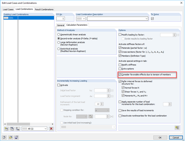
Do I have to activate the favorable effect due to tensile forces when calculating a structural system with tension members according to the second-order analysis?
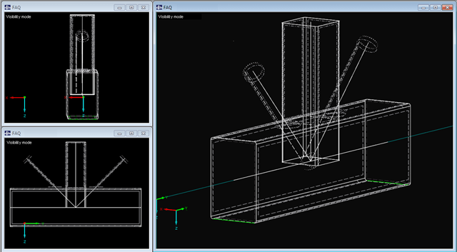
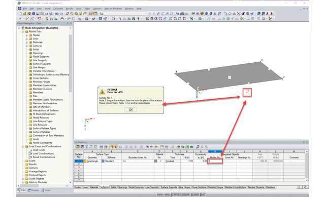
I have a truss node with several rectangular hollow cross-sections connected (modeled as an FE shell structure). To create a realistic connection, it is necessary to remove the surface parts lying in the node from some cross-sections.I achieved this using intersections and deactivating the corresponding surface parts. This significantly slows down work with the model. Is there any other way to generate the node?
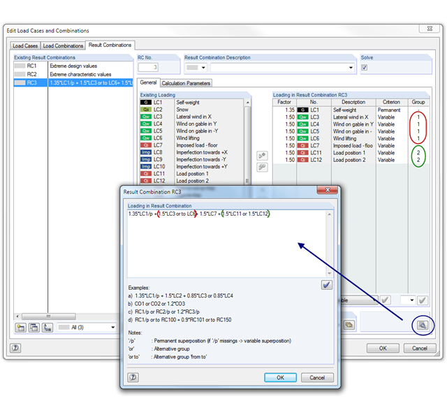
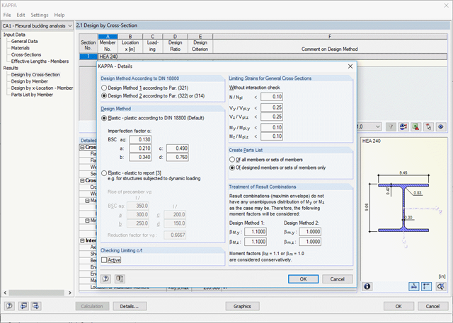
The result combinations calculated in RSTAB include the minimum and maximum values as well as the corresponding internal forces. Why are these internal forces not considered in KAPPA? Which internal forces are used in KAPPA to perform the design?
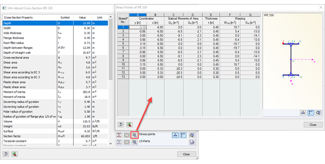
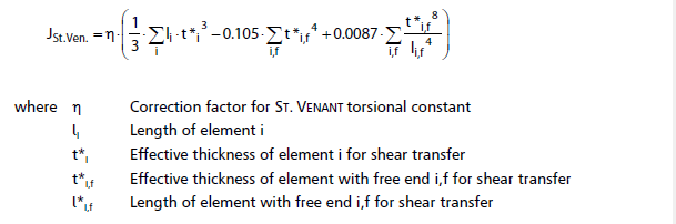
I have only defined one element. If I swap the long and short sides (that is, the thickness becomes the length), the St. Venant torsion constant is, in my opinion, calculated incorrectly.
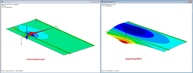
How do you explain a moment distribution such as that seen in Image 01? It looks as if the cantilevered part of the surface is supported at its outer edge, thus resulting in a moment under the concentrated load.